Nonlinearity
The voltage-dependent displacement curves of piezo actuators have a strongly nonlinear course that is subject to hysteresis due to the extrinsic domain contributions. It is therefore not possible to interpolate linearly from the nominal displacement to intermediate positions with a particular driving voltage. The electromechanical and dielectric large-signal curves of piezo ceramics illustrate the characteristics (fig. 1). The origin of each graph is defined by the respective thermally depolarized condition.
The shape of both bipolar large-signal curves is determined by the ferroelectric polarity reversal process when the coercive field strength EC is achieved in the opposing field. The dielectric curve shows very large polarization changes at these reversal points. At the same time, the contraction of the ceramic after reversing the polarity turns into expansion again, since the polarization and the field strength have the same orientation once more. This property gives the electromechanical curve its characteristic butterfly shape. Without the electric field, the remnant polarizations Prem/-Prem and the remnant strain Srem remain.
Piezo actuators are usually driven unipolarly. A semibipolar operation increases the strain amplitude while causing a stronger nonlinearity and hysteresis, which result from the increasing extrinsic domain portions of the displacement signal (fig. 2).
In the datasheets, the free displacements of the actuators are given at nominal voltage.

Standard Layer Heights
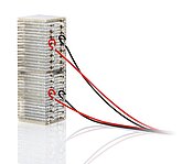
>> PICMA® Stack 60 µm
>> PICMA® Bender 20 to 30 µm
>> PICA Stack/Thru 0.5 mm
>> PICA Shear 0.5 mm
>> Picoactuator® 0.38 mm
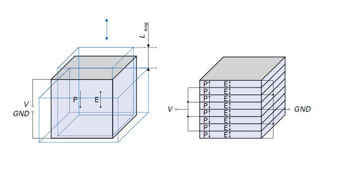
The free displacement of the components that can actually be attained depends on further factors such as the mechanical preload, the temperature, the control frequency, the dimensions, and the amount of passive material.

Piezoelectric Deformation Coefficient (Piezo Modulus)
The gradient ΔS/ΔE between the two reversal points of the nonlinear hysteresis curves is defined as the piezoelectric large-signal deformation coefficients d(GS) (fig. 2). As the progressive course of the curves shows, these coefficients normally increase along with the field amplitude (fig. 3).
Estimation of the Expected Displacement
The values from fig. 3 can be used to estimate the attainable displacement at a particular piezo voltage (see equations for estimating the >> Displacement of Piezo Actuators). The field strength can be calculated from the layer heights of the specific component and the drive voltage VPP.
Hysteresis
In open-loop, voltage-controlled operation, the displacement curves of piezo actuators show a strong hysteresis (fig. 5), which usually rises with an increasing voltage or field strength. Especially high values result for shear actuators or with bipolar control. The reason for these values is the increasing involvement of extrinsic polarity reversal processes in the overall signal.


Creep
Creep describes the change in the displacement over time with an unchanged drive voltage. The creep speed decreases logarithmically over time. The same material properties that are responsible for the hysteresis also cause the creep behavior:


Hysteresis and creep of piezo actuators can be eliminated most effectively through position control in a closed servo loop. To build position-controlled systems, the PI Ceramic piezo actuators of the PICA Stack and PICA Power product line can be optionally offered with applied strain gauges. In applications with purely dynamic control, hysteresis can be effectively reduced to values of 1 to 2 % even without closed-loop control by using a charge-control amplifier.
PI (Physik Instrumente GmbH) offers a wide range of position-controlled piezo systems with capacitive sensors or strain gauge sensors. When the actuator and sensor are combined with suitable guiding mechanics, a low-noise amplifier and corresponding control algorithms, these systems achieve positioning accuracies in the subnanometer range.